

In EKS IPV4 clusters, IP exhaustion problem can be solved by setting up a VPC secondary network. In this blog we will look at step by step guide for setting up EKS cluster using secondary IP ranges.
Need for VPC Secondary Network
Before we jump to the hands on section, lets first understand the need for VPC secondary network configuration for IPV4 clusters.
When you launch a EKS cluster, by default it uses the VPC subnet IP addresses for pods and services. Meaning, if the VPC CIDR is 10.0.0.0/20 (4,096 IPs), the node IPs, pod IPs and service IPs are assigned from CIDR range.
It is not an issue for small clusters with less workloads. However, for large organizations using IPV4 with hybrid cloud networks this could be an issue.
In such organizations when you request for large IP ranges for Kubernetes clusters., network teams often express concerns. Because they need to allocate IP address for multiple clusters in multiple environments and for multiple teams.
You can mitigate the IPv4 exhaustion issue by using AWS VPC secondary IP ranges such as shared address space 100.64.0.0/16 or 172.x series.
If you look at the following image, the Primary ENI of worker nodes use the primary subnet CIDR and pods uses the ENI from the secondary CIDR range.
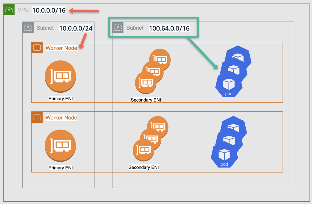
Image src: aws.github.io
A good thing is, you can re-use the secondary ranges in other clusters and the primary ENI does the source network translation and the traffic going outside the cluster uses the primary ENI as source address. So you will not face any routing issues.
Note: You can use CNI plugins like calico to mitigate this issue. But for external CNI plugins you will not get any support from AWS.
Secondary Network setup is not required for the following.
- If you are implementing IPv6 based clusters.
- Private NAT Gateway implementation where VPCs can have overlapping IP addresses.
EKS Secondary Network Setup
Let's have a look at what is the secondary network in the Kubernetes cluster.
Here we use a single dedicated VPC with two different CIDR ranges, which I am considering 192.168.0.0/16 as a primary range for nodes and 100.64.0.0/16 as the secondary range for the pods.
Step 1: Create a VPC and Associate a Secondary CIDR
We are using AWS CLI commands to create the VPC. So some utilities required are given below.
- AWS CLI
- jq
Create a VPC with a CIDR range 192.168.0.0/16. We use this range to create the nodes.
export VPC_ID=$(aws ec2 create-vpc --cidr-block 192.168.0.0/16 --tag-specifications 'ResourceType=vpc,Tags=[{Key=Name,Value=EKS-VPC}]' --query 'Vpc.VpcId' --output text)
Add secondary CIDR 100.64.0.0/16 to the VPC. This range is for creating pods.
aws ec2 associate-vpc-cidr-block --vpc-id $VPC_ID --cidr-block 100.64.0.0/16Create an Internet Gateway for the VPC to get internet access.
export IGW_ID=$(aws ec2 create-internet-gateway --tag-specifications 'ResourceType=internet-gateway,Tags=[{Key=Name,Value=EKS-IGW}]' --query 'InternetGateway.InternetGatewayId' --output text)Attach Internet Gateway to the intended VPC
aws ec2 attach-internet-gateway --vpc-id ${VPC_ID} --internet-gateway-id ${IGW_ID}Create a route table for our subnets.
export RTB_ID=$(aws ec2 create-route-table --vpc-id $VPC_ID --tag-specifications 'ResourceType=route-table,Tags=[{Key=Name,Value=EKS-RouteTable}]' --query 'RouteTable.RouteTableId' --output text)Add route to the internet by attaching IGW in the route table.
aws ec2 create-route --route-table-id ${RTB_ID} --destination-cidr-block 0.0.0.0/0 --gateway-id ${RTB_ID}Set up environment variables for availability zones.
AZ_1="us-west-2a"
AZ_2="us-west-2b"
AZ_3="us-west-2c"
Create subnets for nodes from range 192.168.0.0/16, each in a different availability zone.
SUBNET_ID_NODE_1=$(aws ec2 create-subnet --vpc-id $VPC_ID --cidr-block 192.168.0.0/19 --availability-zone $AZ_1 --tag-specifications 'ResourceType=subnet,Tags=[{Key=Name,Value=Node-Subnet-1}]' | jq -r '.Subnet.SubnetId')

SUBNET_ID_NODE_2=$(aws ec2 create-subnet --vpc-id $VPC_ID --cidr-block 192.168.32.0/19 --availability-zone $AZ_2 --tag-specifications 'ResourceType=subnet,Tags=[{Key=Name,Value=Node-Subnet-2}]' | jq -r '.Subnet.SubnetId')

SUBNET_ID_NODE_3=$(aws ec2 create-subnet --vpc-id $VPC_ID --cidr-block 192.168.64.0/19 --availability-zone $AZ_3 --tag-specifications 'ResourceType=subnet,Tags=[{Key=Name,Value=Node-Subnet-3}]' | jq -r '.Subnet.SubnetId')
Create three subnets for pods from CIDR 100.64.0.0/16.
SUBNET_ID_POD_1=$(aws ec2 create-subnet --vpc-id $VPC_ID --cidr-block 100.64.0.0/19 --availability-zone $AZ_1 --tag-specifications 'ResourceType=subnet,Tags=[{Key=Name,Value=Pod-Subnet-1}]' | jq -r '.Subnet.SubnetId')


SUBNET_ID_POD_2=$(aws ec2 create-subnet --vpc-id $VPC_ID --cidr-block 100.64.32.0/19 --availability-zone $AZ_2 --tag-specifications 'ResourceType=subnet,Tags=[{Key=Name,Value=Pod-Subnet-2}]' | jq -r '.Subnet.SubnetId')


SUBNET_ID_POD_3=$(aws ec2 create-subnet --vpc-id $VPC_ID --cidr-block 100.64.64.0/19 --availability-zone $AZ_3 --tag-specifications 'ResourceType=subnet,Tags=[{Key=Name,Value=Pod-Subnet-3}]' | jq -r '.Subnet.SubnetId')
Associate each subnet with the routing table.
aws ec2 associate-route-table --subnet-id $SUBNET_ID_NODE_1 --route-table-id $RTB_ID
aws ec2 associate-route-table --subnet-id $SUBNET_ID_NODE_2 --route-table-id $RTB_ID
aws ec2 associate-route-table --subnet-id $SUBNET_ID_NODE_3 --route-table-id $RTB_ID

aws ec2 associate-route-table --subnet-id $SUBNET_ID_POD_1 --route-table-id $RTB_ID
aws ec2 associate-route-table --subnet-id $SUBNET_ID_POD_2 --route-table-id $RTB_ID
aws ec2 associate-route-table --subnet-id $SUBNET_ID_POD_3 --route-table-id $RTB_ID
Enable auto-assign public IPv4 address to all subnets. this is required to automatically assign a public IP address to all nodes.
aws ec2 modify-subnet-attribute --subnet-id $SUBNET_ID_NODE_1 --map-public-ip-on-launch
aws ec2 modify-subnet-attribute --subnet-id $SUBNET_ID_NODE_2 --map-public-ip-on-launch
aws ec2 modify-subnet-attribute --subnet-id $SUBNET_ID_NODE_3 --map-public-ip-on-launch

aws ec2 modify-subnet-attribute --subnet-id $SUBNET_ID_POD_1 --map-public-ip-on-launch
aws ec2 modify-subnet-attribute --subnet-id $SUBNET_ID_POD_2 --map-public-ip-on-launch
aws ec2 modify-subnet-attribute --subnet-id $SUBNET_ID_POD_3 --map-public-ip-on-launch
If you are dont enable the Enable auto-assign public IPv4 address option, the nodes won't be attached with the EKS cluster.Step 2: Create an EKS Cluster
We use eksctl command line utility to create a cluster in EKS, make sure you have already installed this in your local system.
Create a cluster config file to build an EKS cluster
vim eks-cluster.ymlModify the details as per your requirements.
Here the EKS version we use is v1.28, the latest one, and subnets, created from 192.168.0.0/16 CIDR for nodes.
In the nodeGroups section, choose your instance type, desired capacity, and your public key name. For this setup, we use t3.medium instance type with two nodes.
apiVersion: eksctl.io/v1alpha5
kind: ClusterConfig

metadata:
  name: custom-cluster
  region: us-west-2
  version: "1.28"

vpc:
  subnets:
    public:
      us-west-2a: $SUBNET_ID_NODE_1
      us-west-2b: $SUBNET_ID_NODE_2
      us-west-2c: $SUBNET_ID_NODE_3

nodeGroups:
  - name: ng-spot
    instanceType: t3.medium
    labels: { role: builders }
    minSize: 2
    maxSize: 4
    volumeSize: 30
    desiredCapacity: 2
    ssh:
      allow: true
      publicKeyName: techiescamp
    tags:
      Name: ng-spot
Step 3: Configure AWS VPC CNI Plugin
The VPC CNI Plugin is an add-on that will be available in each node of the clusters. basically, it is a deamonset named aws-node, and will be present in each node. This plugin attaches the Elastic Network Interface (ENI) to the nodes and assigns private IPs for pods from the VPC.
We have to make some modifications in the CNI configuration for pods to use the secondary CIDR range.
Prerequisites:
- VPC-CNI v1.15.3
The EKS cluster will already have vpc-cni add-on in the cluster, but the version might not be suitable. so to verify the existing EKS CNI version, use the following command.
kubectl describe daemonset aws-node --namespace kube-system | grep Image | cut -d "/" -f 2Ensure the CNI plugin version is suitable for the EKS cluster version. To know more about the recommended version, please visit the official documentation.
If you are using the latest version of EKS (v1.28), the VPC CNI version should be (v1.15.3), otherwise, the pods take the IPs from the primary network.
In multiple ways, we can install or update the VPC CNI plugin. here we show one method to install the latest CNI plugin using eksctl utility.
Verify the add-ons, which are available for the EKS cluster.
eksctl utils describe-addon-versions --kubernetes-version 1.28 | grep AddonNameTo install the vpc-cni add-on, use the following command.
eksctl create addon --cluster custom-cluster --name vpc-cni --version v1.15.3-eksbuild.1 \
    --service-account-role-arn arn:aws:iam::814200988517:role/eksctl-custom-cluster-cluster-ServiceRole-48dmfzxgMzcx --force
Change the custom-cluster to your cluster name and also modify the add-on name vpc-cni and its version v1.15.3, if necessary.
The cluster service account IAM role ARN is necessary for this configuration. you can get this from IAM roles by searching cluster-ServiceRole.
To enable the custom network configurations, set up env for AWS VPC CNI daemon.
kubectl set env daemonset aws-node -n kube-system AWS_VPC_K8S_CNI_CUSTOM_NETWORK_CFG=trueTo set up the env for the AWS VPC CNI config label, use the following command.
kubectl set env daemonset aws-node -n kube-system ENI_CONFIG_LABEL_DEF=failure-domain.beta.kubernetes.io/zoneCreate and apply EKS Custom Resource (CR) for ENIConfig resources.
cat <<EOF  | kubectl apply -f -
apiVersion: crd.k8s.amazonaws.com/v1alpha1
kind: ENIConfig
metadata:
 name: $AZ_1
spec:
  securityGroups:
    - sg-0b2df31a3a4aa9b25
  subnet: $SUBNET_ID_POD_1
EOF

cat <<EOF | kubectl apply -f -
apiVersion: crd.k8s.amazonaws.com/v1alpha1
kind: ENIConfig
metadata:
 name: $AZ_2
spec:
  securityGroups:
    - sg-0b2df31a3a4aa9b25
  subnet: $SUBNET_ID_POD_2
EOF

cat <<EOF | kubectl apply -f -
apiVersion: crd.k8s.amazonaws.com/v1alpha1
kind: ENIConfig
metadata:
 name: $AZ_3
spec:
  securityGroups:
    - sg-0b2df31a3a4aa9b25
  subnet: $SUBNET_ID_POD_3
EOF
Replace the security group ID sg-0b2df31a3a4aa9b25 with your EKS clusters' security group ID. you can find this from the EKS console, networking section.
Step 4: Recreate Nodes
The existing nodes should be terminated and create new nodes. This is required to reflect the CNI configuration changes to the nodes, until then your pods won't get the IPs from the secondary range.
To get the node name and details, use the following command.
kubectl get nodesYou will get the node name from this command output.
To Cordon, the nodes, use the following command.
kubectl cordon ip-192-168-0-102.us-west-2.compute.internalThis command will stop scheduling pods to this node.
Replace it ip-192-168-0-102.us-west-2.compute.internal with your node name.
Drain the node to reschedule all the pods from this node to another node.
kubectl drain ip-192-168-0-102.us-west-2.compute.internal --ignore-daemonsetsFind the instance ID, which you want to terminate.
INSTANCE_ID=$(kubectl get node ip-192-168-0-102.us-west-2.compute.internal -o jsonpath='{.spec.providerID}' | awk -F '/' '{print $NF}')To terminate the instance use the following command.
aws ec2 terminate-instances --instance-ids $INSTANCE_ID --region us-west-2Now this instance is deleted and a new instance will be created automatically. because nodes are bound with an Auto Scaling Group.
To view the list of nodes and their details.
kubectl get nodesTo test the setup, deploy the nginx web server in the nodes.
kubectl create deployment nginx-test --image=nginx --replicas=3To view the list of pods, use the following command.
kubectl get pods -o wideYou will get an output similar to this and ensure all the pods are working fine.
NAME                                READY   STATUS    RESTARTS   AGE     IP              NODE                                           NOMINATED NODE   READINESS GATES
nginx-deployment-7c79c4bf97-4bwbw   1/1     Running   0          6m52s   100.64.74.80    ip-192-168-70-175.us-west-2.compute.internal   <none>           <none>
nginx-deployment-7c79c4bf97-bnxfw   1/1     Running   0          6m52s   100.64.80.90    ip-192-168-70-175.us-west-2.compute.internal   <none>           <none>
nginx-deployment-7c79c4bf97-v25hp   1/1     Running   0          21m     100.64.80.140   ip-192-168-70-175.us-west-2.compute.internal   <none>           <none>
Conclusion
I have tried out this setup to understand how to attach the multiple CIDR networks to a VPC to manage a EKS cluster.
You can further improve the setup for your requirements and also keep in mind that there is a calculation in how many pods you can create in a node depending on how many ENI support with the instance type.
In this setup, I have explained a few things about the vpc-cni, but there are many functionalities available there, so if you are interested to know more about that, please refer to this document.
